To achieve reliable connections with Shin-Etsu Inter-Connectors, certain rules are to be followed regarding the design of the Inter-Connector, it’s application and it’s usage. For elastomeric Inter-Connector, proper holder constructions and certain compression have to be considered carefully in combination with guidance to align the substrates.
Compression and resistance characteristics:
To achieve a stable resistance with elastomeric Inter-Connectors, a certain compression has to be applied to the Inter-Connector to create a chain connection between conductive particles inside the Inter-Connector and provide proper contact pressure towards the substrates. For the wire types of elastomeric Inter-Connectors, the compression provides the required contact pressure from the wires to the substrates.
Alignment, pitch and skew:
Overall tolerances of the assembly construction dominate the choice of the type of Inter-Connector and it’s pitch and height. A general rule is to have 4 to 5 carbon conductive lines per substrate contact to provide stable resistances over the contacts. For metal based Inter-Connectors, the required resistance and current density have to be considered to fix the most suitable type of Inter-Connector and its dimensions in combination with the design of contact patterning on the substrates.
Besides the alignment tolerances of the assembly, the skew of the Inter-Connector has to be considered to specify the Inter-Connector and assembly. Skew is defined as the angle offset of the perpendicular direction of the conductive layers of an Inter-Connector.
Inter-Connector and holder construction:
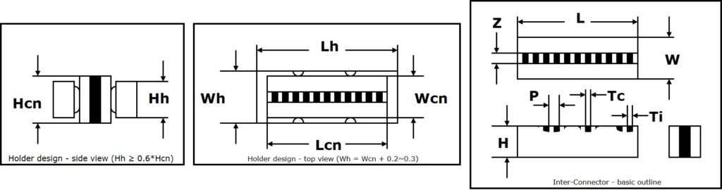
Due to applied Z-axis compression, elastomeric Inter-Connectors will expand in the X-axis and Y-axis. The volume of the compressed Inter-Connector is same as the volume of the uncompressed Inter-Connector. Only sponge silicone rubber sections of the Inter-Connectors can absorb some volume reduction. To guarantee stable compression and avoiding collapses, proper holders are recommended in combination with special design rules for the Inter-Connector itself.
Compression forces and Young’s modulus:
Applicable forces to compress the elastomeric Inter-Connectors can be achieved by using Young’s models.
Load = (A*Z + B*(W – Z))L*C/100
Load: required compression force (N)
Z: conductive core of the Inter-Connectors (mm)
W: width of the Inter-Connector (mm)
L: length of the Inter-Connector (mm)
C: compression rate (%)
A: Young’s modulus of the conductive core (N/mm2)
B: Young’s modulus of the support material (N/mm2)
| Young's Modulus (parameter A) | |
|---|---|
| Carbon core 0.25P | 9.5 N/mm2 |
| Carbon core 0.18P | 8 N/mm2 |
| Carbon core 0.1P | 7.5 N/mm2 |
| Carbon core 0.05P | 7.3 N/mm2 |
| Young's Modulus (parameter B) | |
|---|---|
| SS-type support material (SS-20) | 1.3 N/mm2 |
| SG-type support material (SPO-951) | 1.3 N/mm2 |
| SP-type support material | 1.3 N/mm2 |